Some years ago, I started what is the toughest project I have worked on: I decided to measure the small change in the wavelength of light when emitted from a moving source. Being not a scientist but a simple software programmer, this happens to be a really hard task.
After a few years of trials, today I have a good idea of what I need to complete this project. I have already built some of the necessary assemblies, but honestly, they are pretty bad. I don’t mean they look bad (what they do), but they work badly. The alignment of the beams is complicated. Also, due to what I think is thermal drift I have to re-align the mirrors every 5 minutes to keep the interferometer working. Even worst, the whole setup must lay on the floor for better stability, so all this work should be done in a very uncomfortable position. I will be lucky if I don’t get permanent injuries in the process.
So, I decided to stop, rethink the whole thing, and start again. The idea is to work every component independently and work on them until getting reasonable stability and ease of use. This, in turn, will let me save more data, which means clearer results.
The experiment
(Detailed documentation of this project on Github)
What I need is to measure the small change in the wavelength of a moving source of light. To do this, I use an unbalanced Michelson interferometer. This is a Michelson interferometer where its arms are different in length. This is crucial because that difference acts as a sort of wavelength amplifier. The expected change in wavelength is so small that we will need to amplify it as much as possible, so I made the short arm just a couple centimeters long, and the long arm around 8 meters long (this is why the whole experiment rest on the floor). With this setup, the measured phase shift (after the multiplication effect) is around 0.1 wavelengths. This is easy to see using an oscilloscope.
If you have worked with interferometers, you probably know the floor is not the best place to play with them. Every single vibration is perceived as a change in the interference fringes. This means must of the time you will see moving fringes instead of a stable one (as desired). This is bad, but my design let us get the phase difference between two independent interfering beams, which lets us overcome this limitation.
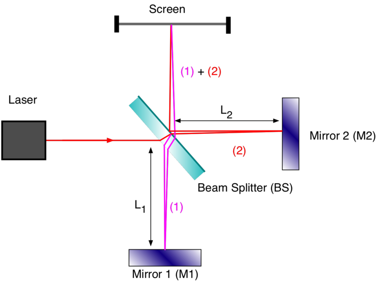
Michelson interferometer scheme (Wikipedia commons)
The two beams interferometer
On a Michelson interferometer, we usually shine a single laser beam. However in this particular experiment is way better to use two laser beams, in order to get the difference between two interferences, which is useful to get rid of the pesky floor vibrations. Strictly speaking, the vibrations never go away, but you can take your measurements without being affected by them. Given that both beams traverse the same path in the interferometer, they both exhibit the same vibrations, and that means they should be in phase. If there is a difference (which I expect) we should see a phase shift between both signals, and we can measure that difference.
The floor vibrations, however, are too fast to be seen with the naked eye, so we use a photodiode and an oscilloscope to see them. But as soon as you got this signal you will notice that they are way too slow to be useful. As crazy as this could sound, I had to increase the vibrations! A small geared motor hanging from the interferometer do the trick. Now we have sinusoidal signals on the oscilloscope, so we can measure the phase difference.
However, the geared motor has one disadvantage: it vibrates (good) but does not let us know in what direction it is moving at a particular time. And happens this is important, because we should get some phase shift if it is moving in one direction, and get the opposite (negative) phase shift if it moves in the opposite direction. Also, the velocity of the moving mirror changes direction, what makes signal distinction complicated. If we know in what direction the oscillating mirror is moving we can easily separate one phase shift from the other.
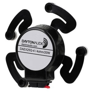
Audio exciter (Parts Express)
So, I had to look for a suitable replacement: a voice coil. Parts Express has a range of audio exciters that fit the bill, at very low cost. A simple amplifier feed by the AWG (Arbitrary Wave Generator) port of my Picoscope 2204A run the audio exciter at the desired frequency (120Hz), and with the required amplitude to generate a sinusoidal signal on the oscilloscope.
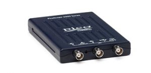
Picoscope (Picotech)
Saving data
In order to analyze the so obtained waveforms, we must save them. To me, the most friendly and cost-effective way of doing this is by using a Haasoscope. This is an open-source oscilloscope with both excellent capabilities and low cost. A Python user software let me tweak the oscilloscope to save the data as soon as possible, what in the end let me get 120 readings per second (it could go faster, but restrictions apply). Each reading contains 4 waveforms (2 interferometer signals, 1 slider position signal, 1 audio exciter signal). Each waveform is 128 samples wide.
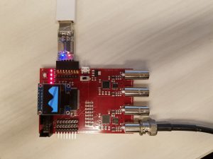
Haasoscope (CrowdSupply)
However, due to mechanical vibrations on the slider (due to braking), the data read near zero velocity is too noisy to be useful. Later on, I found the noise could be reduced with better mechanical design of the system, so finally I could save samples also when the slider was near rest.
(This is a work in progress, last updated on June 1st, 2020)